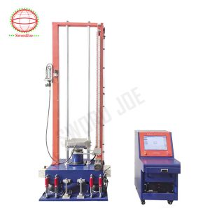
Pneumatic Mechanical Shock Testing System For Transducer Industry
A mechanical shock tester is a device used to simulate and measure the impact of sudden mechanical shocks on products, verifying their ability to withstand such forces without damage.
- Shock Simulation: Reproduces real-world shock scenarios, such as drops, collisions, or transportation vibrations, in a controlled environment.
- Performance Testing: Evaluates whether products (e.g., electronics, automotive parts) maintain functionality and structural integrity after shock exposure.
- Data Acquisition: Records key parameters like shock acceleration, duration, and direction to quantify the impact intensity and product response.
Different testers are designed for specific shock modes, with the main categories listed below:
These parameters determine the tester’s capabilities and suitability for specific tests:
- Shock Acceleration: The maximum acceleration the tester can generate, usually measured in g-force (g) (1g ≈ 9.8 m/s²).
- Shock Duration: The length of time the shock pulse lasts, typically ranging from 0.1 ms–100 ms; shorter durations correspond to more intense, instantaneous impacts.
- Shock Pulse Shape: The waveform of the shock, with the most common types being
- half-sine wave (simulating soft impacts),
- square wave (simulating rigid collisions), and
- sawtooth wave (simulating sudden stops).
- Electronics: Testing smartphones, laptops, and circuit boards to ensure they survive drops or transportation shocks.
- Automotive: Verifying the durability of airbags, sensors, and engine parts under collision or vibration conditions.
- Aerospace: Validating the resistance of avionics and satellite components to launch or landing shocks.
- Packaging: Assessing whether packaging materials (cartons, foam) can protect products during shipping and handling.
| Model | IS5 | IS10 | IS25 | IS50 | IS100 | IS200 | IS300 |
| Maximum test load (kg) | 5 | 10 | 25 | 50 | 100 | 200 | 300 |
| Table size (mm*mm) | 120*120 | 200*200 | 350*350 | 500*500 | 700*700 | 750*750 | 800*800 |
| Shock waveform (m/s²) |
|
| Half sine waveform | 100~30000 | 100~20000 | 100~10000 | 100~6500 | 150~6000 | 150~5000 | 150~3500 |
| After peak saw-tooth | 100~1000 | 100~1000 | 100~1000 | 100~1000 | 100~1000 | 150~1000 | 150~1000 |
| Trapezoidal wave | 150~1500 | 150~1500 | 150~1200 | 150~1200 | 150~1200 | 150~1000 | 100~1000 |
| Pulse duration time (m/s) |
|
| Half sine waveform | 0.5~20 | 0.6~20 | 0.8~20 | 1.5~20 | 2~20 | 2.5~20 | 3~20 |
| After peak saw-tooth | 6~18 | 6~18 | 6~18 | 6~18 | 6~18 | 6~18 | 6~18 |
| Trapezoidal wave | 6~20 | 6~20 | 6~20 | 6~25 | 6~25 | 6~25 | 6~25 |
| Maximum impact distance (mm) | 1550 | 1500 | 1400 |
| Anti-secondary impact device | Air pressure friction brake | Hydraulic friction brake |
| Table weight (kg) | 1300 | 1500 | 2800 | 3800 | 4350 | 4900 | 6250 |
| Dimensions (L*W*H)(mm) | 900*450*2600 | 1000*500*2700 | 1100*800*2800 | 1100*750*2800 | 1350*850*2850 | 1420*920*2900 | 1480*1000*2950 |
| Control and measurement system | OKS01 |
| Power requirements | 220V±10% single phase AC 50Hz 2kVA |
| Hydraulic pump station power requirements | 380V±10% 3 phases AC 50Hz |
| Hydraulic pump station power consumption (kVA) | 2.5 | 2.5 | 4 | 4.6 | 4.6 | 6.2 | 6.5 |
| Applicable standard | GB/T2433.5,GB/T2423.6,IEC68-2-29,JJG497-200 |